 Interior Network Infrastructure
Geoff Huston, July 1994
Copyright (c) Geoff Huston, 1994
 Interior Network Infrastructure
Having examined the national network structure from the perspective of the client and peer interface boundaries, the next section examines relevant issues concerning internal network structure design.
 Interior Network Infrastructure
- Bandwidth is a coarse control tool
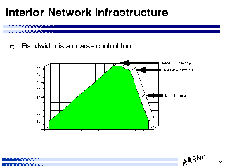
Typically internal network design is a tradeoff between affordable capacity and demand levels. Within this tradeoff the penalties associated with inadequate capacity are harsh within a TCP transport environment.
The behaviour of the TCP end to end retransmission algorithms are tolerant of packet delay and packet loss only within relatively small parameters of variability. At the onset of congestion queues within the routers start to form, and the variability in round trip time increases exponentially. Such a high level of variability in round trip times causes TCP to retransmit stream segments which may still be blocked in the queue waiting for line access, adding further pressure to the queue resources. While a simple approach may be to lengthen the queue this will act as further pressure on increased variability on round trip times, so a typical performance design choice is to limit the router queue size, using TCP lost packet recovery timers as an alternative to increasing the recorded round trip times.
The effective outcome of this situation is that once imposed load on a link exceeds some 80% (this figure is an approximation - the value quoted in many analyses ranges from 60% to 80% depending on sample time, queue length and link bandwidth) of available link capacity, then further imposed load will cause the effective throughput (acknowledged data) to drop dramatically, effectively prolonging the congestion event and drastically reducing actual network capacity.
The conclusion drawn from this is that the deliberate use of available bandwidth as a control mechanism on demand growth is a very poor strategy, as the resultant (effectively planned) congestion situation results in very severe performance penalties, and in looking at the unit cost of delivered data, the resultant drop in actual data throughput through a constant priced network link is in effect a steep rise in the unit cost of the data.
 Network Infrastructure
      - Engineer capacity for peak demand periods
      - Understand end-to-end flow patterns
      - Attempt to avoid sustained (> 15 minutes) acute congestion on any link
      - Constantly monitor bandwidth utilisation and flow patterns
      - Generate trend patterns and plan accordingly
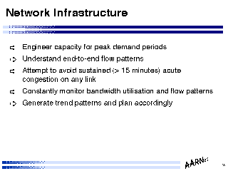
In order to design an effective network infrastructure in terms of capacity planning, it is necessary to engineer adequate capacity to allow peak time usage to be supported on the network without sustained congestion intervals if the network is to support the actual demand levels.
It is also necessary to understand end-to-end flow patterns, and engineer minimal delay paths and adequate capacity to support such flows. Here a typical profile of end to end flows within many national infrastructures does conform within some level of approximation to population centres, although with the capacity of desktop workstations to generate megabit flow demands particular user programs may distort this pattern.
 Network Infrastructure
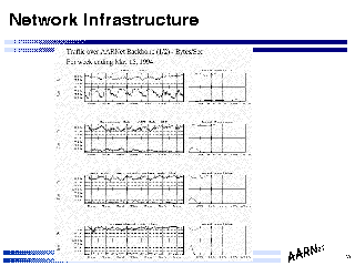
The consequent operational management requirement is to constantly monitor actual link usage levels at a level of granularity which allows identification of sustained peak load incidents.
It also implies a requirement to map this data into a trend data set, which allows a level of predicability of traffic growth levels, which should provide sufficient information to allow capacity planning to take place within a framework which is mapped to actual demand levels.
 Network Infrastructure
      - Communications technology choices:
             Dedicated Facilities
                 point to point leased circuit
                 point to point radio
             Common Switched Facilities
                 X.25
                 Frame Relay
                 SMDS access
                 ATM
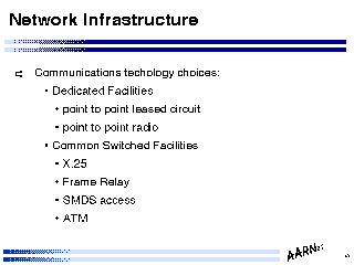
The options for capacity provisioning generally fall within two distinct communications models: the provisioning of dedicated point to point capacity, and the use if shared access switching technologies. Some available transport technologies are enumerated above. In effect the choice of which transport technologies to use within a particular configuration is a tradeoff between availability of service within the domain of intended deployment, cost of access to the technology, cost of use of the technology, and performance and reliability metrics of the technology.
As the use of router technology allows the network service provider to regard all such technologies as a packet transit mechanism there is no requirement to uniformly deploy any particular transport technology across the entire network internal infrastructure and each logical component of the configuration can be treated, to some extent, individually in order to arrive at the optimal choice.
The assumption made within the following notes is that the network service provider operates within an environment of purchase of the underlying transmission services. If such a service is being operated by a transmission service operator (such as a telco) there are typically somewhat different considerations to factor into the design choice.
 Network Infrastructure
      - Leased circuit design
             Performance
             Reliability
             (In)Flexibility
             Cost
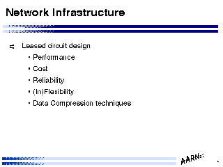
In looking at dedicated point-to-point transmission facilities there are a number of relevant factors which impact choice of particular service offerings.
Such factors typically include:
 Network Infrastructure
      - Hierarchy (Star) Topology
             + Minimal Cost
             + Simple Topology
             + Maximal efficiency
             - Critical points of failure
Within a dedicated circuit infrastructure the associated design requirement is the design of the internal topology of the network.
The major factors which impact on topology choice include circuit availability, circuit cost, end to end flow patterns and circuit reliability.
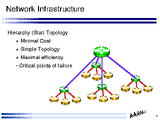
One possible configuration is a minimal spanning tree which covers the client access points and external access points. Such a configuration typically takes the form of single (or multiple) stars, radiating out from major population centres - a hierarchical topology.
Such a topology has a number of advantages, including minimal cost (which considering that circuit costs typically dominate the business profile of a value added bandwidth reseller, as Internet providers are typically characterised, is a major advantage), simple topology (which in turn allows deployment of simple routing configurations, and maximal efficiency of utilisation of circuits (in so far as there is no requirement to attempt to load balance across a mesh using manual balancing via routing protocols.
Working against this is the dual factors of circuit reliability considerations and router availability factors, both of which are compounded by critical points of failure within such topologies.
Whether such a compromise is acceptable is a business decision, where the design engineering activity can determine the relative cost factors and service availability risk factors which are the major inputs to such a decision.
 Network Structure - Example
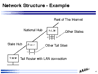
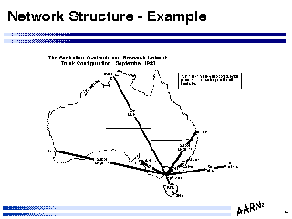
Indicated in the figure is a multiple level hierarchical topology, where a single switching hub feeds trunk lines to a number of regional access hubs, which in turn are concentrators for client access links.
Such designs can be extended to multiple levels of regional access hubs by effectively configuring a "subordinate" regional hub with a single link to a regional hub which in turn is connected to the central switching point.
 Network Structure - Example
Indicated in this figure is the topology of the Australian network engineered by the author, as of December 1993. The cost constraints, and the reliability factors of the circuits, routers and operational environments has allowed the network to be configured as a minimal spanning star trunk topology, feeding regional access hubs which are client connector points, using carrier provided leased dedicated circuits for the trunk network.
Not surprisingly the trunk hub is configured within a major population centre, and houses the points of attachment to external networks.
 Network Infrastructure
      - Mesh Topology
             + Resiliency against link or site failure
             - Higher communications lease cost
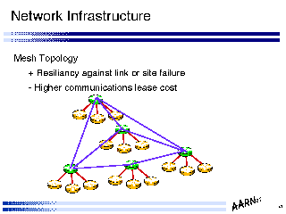
A mesh topology can provide a network with a greater degree of resiliency of service than that provided by the underlying technology base. One of the major technology assets of the internet transport protocol layer is the ability to continue to service a reliable end to end connection as long as the underlying switching fabric allows end to end reachability, even though individual elements of that fabric may shift between available and unavailable states. A mesh topology uses that technology attribute to provide a high resiliency service environment.
This resiliency cannot be provided within all environments. Multiple circuits to a site may use a single carrier bearer system, and even diverse circuits may be configured across a single trunk bearer by the carrier, so that careful engineering and purchase specification is required to ensure that a mesh topology which is susceptible to multiple simultaneous component failure does not carry such susceptible components across a single bearer.
Mesh topologies are typically more expensive than an equivalent minimal spanning topology, even where end to end data flows can be optimally balanced within the mesh. The expense factor lies in the typical consideration that higher capacity circuits are cheaper, on a per kilobit per kilometre per month cost metric, than their equivalent lower capacity circuit, and an equivalent mesh topology with directly comparable total carriage capacity to a minimal spanning topology will generally be cheaper in terms of purchase of transport capability.
A trunk network configuration often uses a resilient mesh structure within the central core of the network, with single spurs serving outlying access points, exhibiting a compromise between full service resiliency and cost factors.
 Network Infrastructure
      - Hybrid - Resiliency via Dial-on-Demand
             Establish backup circuits using ISDN, X.25 or modems
             Issue of matching backup capacity against primary capacity
Circuit mesh topologies is not the only way to engineer service resiliency within an Internet environment. Dial-on-demand services can be configured as an alternative to the static mesh configuration where circuits can be established in response to primary circuit failure.
The environment for dial-on-demand is one where the routing system used can hold-down advertising circuit failure for the period required to establish a dialup data circuit. Typically this is most effective within X.25 and/or ISDN environments where dynamic circuits can be established within a seconds.
The cautionary note to place against dynamically dialled circuit facilities is that such facilities are only useful where the dialled backup circuit capacity is at a level of bandwidth which is directly comparable with the primary circuit bandwidth. Where the dynamically dialled bandwidth is significantly less than the primary capacity the dynamic link will immediately disappear with a case of catastrophic congestion induced collapse, and in such a case lack of connectivity is often a preferable operational situation to "almost, but not all there" connectivity.
Circuit topology models are not inherently fixed topology models: it is always possible to "pull more wire" from point to point in response to growth in traffic levels which strain existing link capacities.
 Network Infrastructure
      - Access to common switched services
             X.25
             Frame Relay
             SMDS
             ATM
An alternative transmission service model is that of access to a common switched service, where connectivity is typically provided through configuration of virtual circuits across the common switched fabric. X.25 is perhaps the most universally deployed switched access technology, and perhaps the hardest technology to use as a base for an Internet. As the flow control and error control characteristics of X.25 are effectively unnecessary from an internet protocol perspective there are some performance hits in using an X.25 substrate for an internet, and considerable care must be taken when establishing virtual circuits across the X.25 network that a virtual circuit does not "double back on itself" across a single X.25 physical circuit. Generally the Internet network service provider, and the X.25 network service provider would be well advised to sit down together and establish how it may be possible to configure the internet with a virtual circuit topology which maps cleanly onto the underlying X.25 physical network topology.
Frame Relay does offer some advantages over the use of X.25, such that the internal flow control and internal error correction on a gateway to gateway have been removed from the Frame Relay support, and accordingly it is potentially a more efficient structure to layer an Internet above a Frame Relay service. However the issue of committed information rates, burst traffic support levels, and of course tariff all play a part in determining the suitability of the service.
SMDS services are just being introduced into the Internet support environment in many cases, and the motivational factor for SMDS generally centres around scalable access speeds, rather than any inherent carriage characteristic of SMDS which is in some way unique and special way.
At this stage ATM is perhaps removable from this list, in so far as it does not form an integral part of many network service infrastructure technologies today, and its inclusion here is as much as expression of some form of faith that ATM will be a technology of choice in future high speed infrastructure services.
 Network Infrastructure
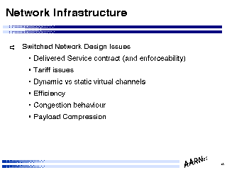
      - Switched Network Design Issues
            Delivered Service contract (and enforceability)
            Tariff issues
            Dynamic vs static virtual channels
            Efficiency
            Congestion behaviour
The issues associated with network design across shared switching infrastructure are somewhat different to dedicated circuit design issues. Within a switched infrastructure topology considerations are much less relevant as a design issue in so far as new circuits can be configured, and removed, with ease, and although current routers do not bring up a new circuit automatically (as this is typically a configuration issue which does entail additional expenditure the task is generally a manual configuration task as a consequence.
That is not intended to imply that such technologies are otherwise relatively simple to deploy, as this is not the case. The design issues which are specific to switched transport technologies include the issue of performance, and the means of enforcement of performance levels. Here there is no dedicated end to end channel and associated single master data clock as the means of enforcing data throughput levels, as the switched network uses a customer access data clock, but internal data throughput levels are typically specified as a contract rather than through some technical aspect of the underlying switching technology. In effect it is the customer contract and the contract enforcement mechanism which is an integral component of the Internet network service environment.
Generally tariffs are lower within this environment for a given end to end transport capability, reflecting both the capability to share a common transport environment across a number of customers, and the issues associated with obtaining sustained transport capability at the configured rates.
 Routing within the Network
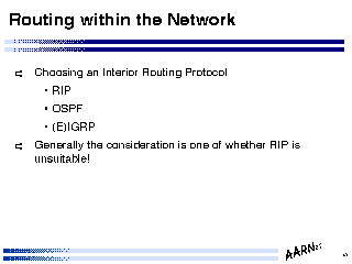
      - Choosing an Interior Routing Protocol
            RIP (2)
            OSPF
            (E)IGRP
      - Generally the consideration is one of whether RIP is unsuitable!
Across the internal connectivity topology the network service provider must operate an internal routing protocol. It is noted that in general the choice of which protocol to use in this domain is a choice made independently of the choice of protocols to use as the client interface address exchange protocol, and independently of the choice of protocol to uses and the exterior peer interface routing protocol.
The parameters of this decision are ease of installation and operation and adaptability of the protocol to match the network's individual requirements and the environment of the network.
Here again the guideline of ultimate simplicity indicates that the starting point is to consider how and why RIP is unsuitable, and if there are no reasons, then RIP is a very suitable candidate from the perspective of simplicity and ease of use. RIP does have a number of problems which imply that the domain of applicability of RIP is a shrinking one. The constant issues of RIP include the time taken for a distance vector protocol to converge to a stable state in the face of either topology changes or external route presentation changes, and the high level of constant information exchange used by the protocol in the steady state (RIP's overheads are directly related to the number of routed entered and carried within the RIP protocol domain). In addition RIP has embedded notions of Class A, B and C networks, so that carrying around aggregated information (the so-called CIDR blocks) of network value and associated mask on a longest match basis is not readily possible within the RIP environment.
Thus while RIP, within a simple, stable topology, routing a small number of networks which are class-based entities, does have a role within a number of networking domains as a readily accessible, cheap routing protocol, this is a statement which may not be constant within the near term future (because of potential changes in class-based address management primarily).
An alternative to RIP is RIP V2, which introduces class-less address family support into the RIP domain. However it must be noted that RIP V2 does not at present enjoy RIP's ubiquity of availability.
Alternatives to RIP also include vendor-proprietary distance vector routing protocols, where a vendor may choose to refine the basic RIP architecture by using mechanisms to avoid count to infinity, information transfer load, broaden the information base for routing decisions beyond simple hop count, and similar issues. Cisco System's IGRP (and E-IGRP, a classless extension of IGRP) are examples of such routing protocol families.
The other routing technology is a link state technology, which is directed at an environment which features fast convergence to underlying topology changes through a view of routing based on topology as the routing determinant. There are a number of link state technology-based routing protocols, including OSPF and IS-IS. OSPF does now enjoy reasonable consensus within the router vendor fraternity as a supported protocol, and OSPF does include support for classless address families and variable length subnet masks on a network. Where OSPF does have a potential problem is in the size of the deployed network, and particularly large networks would be advised to carefully consider whether OSPF can operate effectively across a large unstructured routing space, or whether the imposition of additional routing structure may result in an overall more stable system.
No dynamic protocol will do the entire job! There is always a need to enter routing information in a static manner, and instruct the routing protocol to promulgate this information dynamically across the network's routing domain.
 Routing within the Network
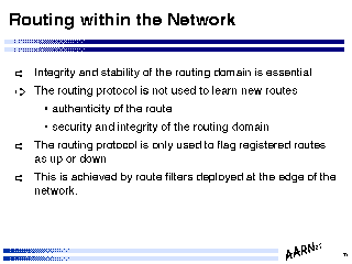
      - Integrity and stability of the routing domain is essential
      - The routing protocol is not used to learn new routes
             authenticity of the route
             security and integrity of the routing domain
      - The routing protocol is only used to flag registered routes as up or down
      - This is achieved by route filters deployed at the edge of the network.
In attempting to engineer a routing domain there are a number of considerations to the national network provider.
The first is that the management of the deployed client address domain is the key role of the network provider - if the addresses are advertised correctly data traffic will flow according to formation. Otherwise there is no service to the client. Thus integrity and stability of the routing domain is essential to the service provider's very service.
The second point is that the routing protocol is not used as a means of discovering new networks. As each client is configured into the network service provider's domain the considerations respecting the client interface effectively implied that the service provider's routers would be manually configured to accept information from the client relating to the client's networks. Dynamic information acceptance implies that the network provider becomes susceptible to the client's routing failures (such as incorrectly advertising reachability to networks) and to the client's other external connections (such as advertising preferential reachabiliy to another client's network. Thus the routing protocol is not used as a firewall for the routing domain of the network service provider. The routing protocol is used to disseminate reachability paths across the network in a reliable and trustable manner.
In addition the routing protocol is used to flag whether a path to a network is available or not, allowing alternate paths to be used if such exist.
All of this is achieved through careful use of routing filters at the edge of the provider's routing domain, intended to ensure that the network service provider is able to construct a reliable and accurate and stable routing domain in a manner which is independent of the clients' routing configurations and behaviour.
 Routing within the Network
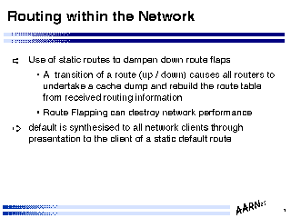
      - Use of static routes to dampen down route flaps
             A transition of a route (up / down) causes all routers to undertake a
                 cache dump and rebuild the route table from received routing information
             Route Flapping can destroy network performance
      - default is synthesised to all network clients through presentation to the
            client of a static default route
The judicious use of static routing techniques can be useful to dampen down the effect of line state transitions - the so called "route flapping" problem. Route transitions cause a dump of the cached routing tables in all routers, which in turn can impact on overall performance of the routing system. There are two ways in which route flapping can be damped.
The first is through use of configured static routes. The configuration uses the network provider's client interface routers to constantly advertise the reachability of the client's network as a static advertisement. The drawback of this configuration is that when the network is unreachable via the provider the traffic will effectively be black-holed at the client interface, causing potentially unnecessary traffic (in practice this is not a major problem in most networks, as the traffic level is usually not significant as there is no backflow of ACKs from the unreachable destination network). The major drawback is where the client is using either multiple connections to the provider, or is using a number of providers for their service, in which case there is a requirement to use dynamic routing exclusively in order to ensure that alternate paths are used in the event of path failure.
The second damping measure is through the use of address aggregation, where failure of a sub-block within the advertised block will not cause large scale perturbations of the routing tables across the network. Again this configuration does have a number of drawbacks, and can only be used effectively in advertising an address block associated with a single client, as the issues of aggregating across multiple clients within the internal provider's routing environment may cause unintended denial of service through inability to perform alternate path selection where multiple paths to the client exist.
The use of a synthesised default allows the client to see a continuous presentation of a single default route. Here the issues of the static default presentation to the client have been addressed in the previous section detailing the design of the client / network service provider interface.
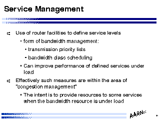 Service Management
      - Use of router facilities to define service levels
             form of bandwidth management:
                 transmission priority lists
                 bandwidth class scheduling
             Can improve performance of defined services under load
      - Effectively such measures are within the area of "congestion management"
             The intent is to provide resources to some services when the bandwidth
                 resource is under  load
Within the internal routing structure is it possible to uniformly configure the routers to undertake traffic prioritisation to enable differing service levels to different classes of traffic. This is a form of bandwidth management, where certain classes of traffic can be placed within a priority queue for access to the underlying transmission resource during periods of contention.
There are two common methodologies for implementing such traffic prioritisation within routing devices. The first is the use of priority queues, where packets are drained from the highest priority queue before scheduling packets that have been placed on lower priority queues. Such preemptive scheduling structures can isolate high priority streams from brief congestion events within the transport level, but do have the side effect of prolonging the congestion event as the lower priority streams typically suffer from prolonged queue lifetimes, with consequent impact on end to end stream control and effective stream throughput.
The second methodology is that of class scheduling, where classes of traffic are effectively assigned a fixed maximum level of access to the underlying transmission resource. For example one class of traffic can be assigned access to 40% of available bandwidth, a second defined class 30% and the remainder 30%. This class scheduling technique will not provide the same level of isolation from congestion periods as full preemptive scheduling, but will effectively minimise the overall impact of congestion on all traffic flows, as all classes of traffic do obtain some level of access to the transmission resource under congestion.
Typically the router allows the provider to define filters to characterise traffic into certain classes. These filters can use source and destination addresses, TCP and UDP ports and packet size within the filter description language, allowing the operator considerable altitude in defining service classes.
The point stressed here is that for such service definition to operate effectively all routers should be configured with the same service management configuration. It should also be noted that such management structures will not enforce service levels across the entire internetwork domain - where traffic is passed to other networks service management structures may differ, and overall end to end performance cannot be engineered unless all peer providers adopt a similar service class management structure.
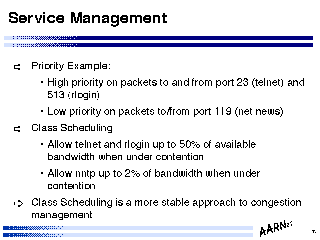 Service Management
      - Priority Example:
             High priority on packets to and from port 23 (telnet) and 513 (rlogin)
             Low priority on packets to/from port 119 (net news)
      - Class Scheduling
             During bandwidth contention periods:
             Allow telnet and rlogin up to 50% of available bandwidth
             Allow nntp up to 2% of bandwidth
      - Class Scheduling is a more stable approach to congestion management
As an example, it is possible to define a pre-emptive queue structure where packets which are sourced from, or destined to the remote interactive access ports (TCP ports 23 for telnet and 513 for rlogin) are placed in a high priority queue, and all packets sourced from, or destined to network news protocol ports (port 199 for nntp) are placed in a low priority queue, and all other packets placed in a medium priority queue. During congestion events interactive access will receive preferential access to the transmission resource, and the congestion event will need to have passed before network news flows will resume.
An alternate configuration uses class scheduling to allow the interactive access streams access to up to 50% of the transmission resource under congestion, and limit the network news flows to no more than 2% of the resource until the congestion event has cleared and the queues are drained.
In general it is asserted that class scheduling allows more rapid recovery from burst congestion events, and is more stable under sustained congestion (although this is only the case where sustained traffic demand is comparable to transmission capacity), while the preemptive scheduling configuration will effectively prolong the congestion event for all classes of traffic except the highest priority traffic, effectively allowing high priority traffic to flow even under sustained congestion events (again this will break down under large scale congestion).
3. Engineering the Network - The Client Interface
4. Engineering the Network - External Peering
5. Engineering the Network - Infrastructure
7. The Operational Environment
GH, July 1994