Papers and Articles
An occasional series of articles on the
social and technical evolution of the Internet
by Geoff Huston

Papers and ArticlesAn occasional series of articles on the
social and technical evolution of the Internet |
June 1998
by Paul Ferguson, Cisco Systems and Geoff Huston, Telstra
In Part I we introduced a working definition of the term "Virtual Private Network" (VPN), and discussed the motivations behind the adoption of such networks. We outlined a framework for describing the various forms of VPNs, and then examined numerous network-layer VPN structures, in particular, that of controlled route leakage and tunneling techniques. We begin Part II with examining other network-layer VPN techniques, and then look at issues that are concerned with non-IP VPNs and Quality-of-Service (QoS) considerations.
This section continues from Part I to look at the various types of VPNs using a taxonomy derived from the layered network architecture model. These types of VPNs segregate the VPN network at the network layer.
A network can be segmented at the network layer to create an end-to-end VPN in numerous ways. In Part I we described a controlled route leakage approach that attempts to perform the segregation only at the edge of the network, using route advertisement control to ensure that each connected network received a view of the network (only peer networks). We pick up the description at this point in this second part of the article.
As outlined in Part I, the alternative to a model of segregation at the edge is to attempt segregation throughout the network, maintaining the integrity of the partitioning of the substrate network into VPN components through the network on a hop-by-hop basis. Part I examined numerous tunneling technologies that can achieve this functionality. Tunneling is also useful in servicing VPN requirements for dial access, and we will resume the description of tunnel-based VPNs at this point. Virtual Private Dial Networks
Although several technologies (vendor-proprietary technologies as well as open, standards-based technologies) are available for constructing a Virtual Private Dial Network (VPDN), there are two principal methods of implementing a VPDN that appear to be increasing in popularity"Layer 2 Tunneling Protocol (L2TP) and Point-to-Point Tunneling Protocol (PPTP) tunnels. From an historical perspective, L2TP is the technical convergence of the earlier Layer 2 Forwarding (L2F) [1] protocol specification and the PPTP protocol. However, one might suggest that because PPTP is now being bundled into the desktop operating system of many of the world"s personal computers, it stands to be quite popular within the market.
At this point it is worthwhile to distinguish the difference between "client-initiated" tunnels and "NAS-initiated" (Network Access Server, otherwise known as a Dial Access Server) tunnels. The former is commonly referred to as "voluntary" tunneling, whereas the latter is commonly referred to as "compulsory" tunneling. In voluntary tunneling, the tunnel is created at the request of the user for a specific purpose; in compulsory tunneling, the tunnel is created without any action from the user, and without allowing the user any choice in the matter.
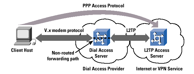
L2TP, as a compulsory tunneling model, is essentially a mechanism to "off-load" a dialup subscriber to another point in the network, or to another network altogether. In this scenario, a subscriber dials into a NAS, and based on a locally configured profile (or a NAS negotiation with a policy server) and successful authentication, a L2TP tunnel is dynamically established to a predetermined endpoint, where the subscriber"s Point-to-Point Protocol (PPP) session is terminated (Figure 1).
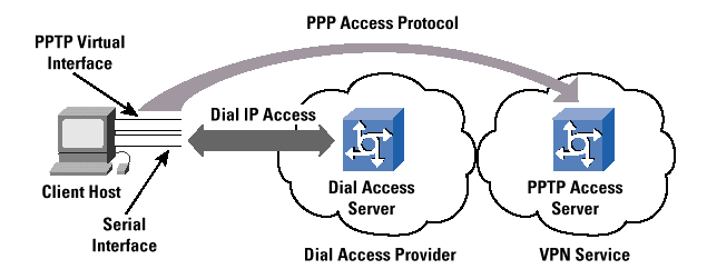
PPTP, as a voluntary tunneling model, on the other hand, allows end systems (for example, desktop computers) to configure and establish individual discrete point-to-point tunnels to arbitrarily located PPTP servers, without the intermediate NAS participating in the PPTP negotiation and subsequent tunnel establishment. In this scenario, a subscriber dials into a NAS, but the PPP session is terminated on the NAS, as in the traditional Internet access PPP model. The layered PPTP session is then established between the client end system and any upstream PPTP server that the client desires to connect to. The only caveats on PPTP connectivity are that the client can reach the PPTP server via conventional routing processes, and that the user has been granted the appropriate privileges on the PPTP server (Figure 2).
Although L2TP and PPTP may sound extraordinarily similar, there are subtle differences that deserve further examination. The applicability of both protocols is very much dependent on what problem is being addressed. It is also about control"who has it, and why it is needed. It also depends heavily on how each protocol implementation is deployed"in either the voluntary or the compulsory tunneling models.
With PPTP in a voluntary tunneling implementation, the dial-in user can choose the PPTP tunnel destination (the PPTP server) after the ini-tial PPP negotiation has completed. This feature is important if the tunnel destination changes frequently, because no modifications are needed to the client"s view of the base PPP access when there is a change in the server and the transit path to the server. It is also a significant advantage that the PPTP tunnels are transparent to the ser-vice provider, and no advance configuration is required between the NAS operator and the overlay dial access VPN. In such a case, the ser-vice provider does not house the PPTP server, and simply passes the PPTP traffic along with the same processing and forwarding policies as all other IP traffic. In fact, this feature should be considered a significant benefit of this approach. The configuration and support of a tunneling mechanism within the service provider network would be one less parameter that the service provider has to operationally man-age, and the PPTP tunnel can transparently span multiple service providers without any explicit service provider configuration. How-ever, the economic downside to this feature for the service provider, of course, is that a "VPDN-enabled" network service can be marketed to yield an additional source of revenue. Where the client undertakes the VPDN connection, there is no direct service provider involvement and no consequent value added to the base access service.
From the subscriber"s perspective, this is a "win-win" situation, because the user is not reliant on the upstream service provider to deliver the VPDN service"at least no more than any user is reliant for basic IP-level connectivity. The other "win" is that the subscriber does not have to pay a higher subscription fee for a VPN service. Of course, the situa-tion changes when the service provider takes an active role in providing the VPDN, such as housing the PPTP servers, or if the subscriber resides within a subnetwork in which the parent organization wants the ser-vice provider"s network to make the decision concerning where tunnels are terminated. The major characterization of PPTP-based VPDN is one of a roaming client base, where the clients of the VPDN use a local con-nection to the public Internet data network, and then overlay a private data tunnel from the client's system to the desired remote service point. Another perspective is to view this approach as "on-demand" VPDN virtual circuits.
With L2TP in a "compulsory" tunneling implementation, the service provider controls where the PPP session is terminated. This setup can be extremely important in situations where the service provider to whom the subscriber is actually dialing into (let"s call it the "modem pool provider" network) must transparently hand off the subscriber"s PPP session to another network (let"s call this network the "content pro-vider"). To the subscriber, it appears as though the local system is directly attached to the content provider"s network, when in fact the access path has been passed transparently through the modem pool provider"s network to the subscribed content service. Very large content providers, for instance, may outsource the provisioning and maintenance of thousands of modem ports to a third-party access provider, who in turn agrees to transparently pass the subscribers" access sessions back to the content provider. This setup is generally called "wholesale dial." The major motivation for such L2TP-based wholesale dial lies in the typical architecture of the Public Switched Telephone Network (PSTN), where the use of wholesale dial facilities can create a more rational PSTN call load pattern with Internet access PSTN calls terminated in the local Central Office.
Of course, if all subscribers who connect to the modem pool provider's network are destined for the same content provider, then there are certainly easier ways to hand this traffic off to the content provider"s network"such as simply aggregating all the traffic in the local Central Office and handing the content provider a "big fat pipe" of the aggregated session traffic streams. However, in situations where the modem pool provider is providing a wholesale dial service for multiple upstream "next-hop" networks, the methods of determining how each subscriber"s traffic must be forwarded to his/her respective content provider are somewhat limited. Packet forwarding decisions could be made at the NAS, based on the source address of the dialup subscriber"s computer. This scenario would allow for traffic to be forwarded along the appropriate path to its ultimate destination, in turn intrinsically providing a virtual connection. However, the use of assigning static IP addresses to dial-in subscribers is highly discouraged because of the inefficiencies in IP address utilization policies, and the critical success of the Dynamic Host Configuration Protocol (DHCP).
There are, however, some serious scaling concerns in deploying a large-scale L2TP network; these concerns revolve around the issue of whether large numbers of tunnels can actually be supported with little or no network performance impact. Since there have been no large-scale deployments of this technology to date, there is no empirical evidence to support or invalidate these concerns.
In some cases, however, appearances are everything"some content providers do not wish for their subscribers to know that when they connect to their service, they have instead been connected to another service provider"s network, and then passed along ultimately to the service to which they have subscribed. In other cases, it is merely designed to be a matter of convenience, so that subscribers do not need to log into a device more than once.
Regrettably, the L2TP draft does not detail all possible implementations or deployment scenarios for the protocol. The basic deployment scenario is quite brief when compared to the rest of the document, and is arguably biased toward the compulsory tunneling model. Nonetheless, there are implementations of L2TP that follow the voluntary tunneling model. To the best of our knowledge, there has never been any intent to exclude this model of operation. In addition, at various recent interoperability workshops, several different implementations of a voluntary L2TP client have been modeled. Nothing in the L2F protocol would prohibit deploying it in a voluntary tunneling manner, but to date it has not been widely implemented. Further, PPTP has also been deployed using the compulsory model in a couple of specific vendor implementations.
In summary, consideration of whether PPTP or L2TP is more appropriate for deployment in a VPDN depends on whether control needs to lie with the service provider or with the subscriber. Indeed, the difference can be characterized with respect to the client of the VPN, where the L2TP model is one of a "wholesale" access provider who has numerous configured client service providers who appear as VPNs on the common dial access system, whereas the PPTP model is one of distributed private access where the client is an individual end user and the VPN structure is that of end-to-end tunnels. One might also suggest that the difference is also a matter of economics, because the L2TP model allows service providers to actually provide a "value-added" service, beyond basic IP-level connectivity, and charge their subscribers accordingly for the ability to access it, thus creating new revenue streams. By contrast, the PPTP model enables distributed reach of the VPN at a much more basic level, enabling corporate VPNs to extend access capabilities without the need for explicit service contracts with a multitude of network access providers.
Encryption technologies are extremely effective in providing the segmentation and virtualization required for VPN connectivity, and they can be deployed at almost any layer of the protocol stack. The evolving standard for network-layer encryption in the Internet is IP Security (IPSec) [3, 4] . (IPSec is actually an architecture"a collection of protocols, authentication, and encryption mechanisms. The IPSec security architecture is described in detail in [3].)
While the Internet Engineering Task Force (IETF) is finalizing the architecture and the associated protocols of IPSec, there is relatively little network-layer encryption being done in the Internet today. However, some vendor proprietary solutions are currently in use. Whereas IPSec has yet to be deployed in any significant volume, it is worthwhile to review the two methods in which network-layer encryption is predominantly implemented. The most secure method for network- layer encryption to be implemented is end-to-end, between participating hosts. End-to-end encryption allows for the highest level of security. The alternative is more commonly referred to as "tunnel mode," in which the encryption is performed only between intermediate devices (routers), and traffic between the end system and the first-hop router is in plaintext. This setup is considerably less secure, because traffic intercepted in transit between the first-hop router and the end system could be compromised. As a more general observation on this security vulnerability, where a VPN architecture is based on tunnels, the addition of encryption to the tunnel still leaves the tunnel ingress and egress points vulnerable, because these points are logically part of the host network as well as being part of the unencrypted VPN network. Any corruption of the operation, or interception of traffic in the clear, at these points will compromise the privacy of the private network.
In the end-to-end encryption scheme, VPN granularity is to the individual end-system level. In the tunnel mode scheme, the VPN granularity is to the subnetwork level. Traffic that transits the encrypted links between participating routers, however, is considered secure. Network-layer encryption, to include IPSec, is merely a subset of a VPN.
A conventional private data network uses a combination of dedicated circuits from a public carrier, together with an additional private communications infrastructure, to construct a network that is completely self-contained. Where the private data network exists within private premises, the network generally uses a dedicated private wiring plant to carry the VPN. Where the private data network extends outside the private boundary of the dedicated circuits, it is typically provisioned for a larger public communications infrastructure by using some form of time-division or frequency-division multiplexing to create the dedicated circuit. The essential characteristic of such circuits is the synchronization of the data clock, such that the sender and receiver pass data at a clocking rate that is fixed by the capacity of the dedicated circuit.
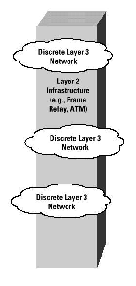
A link-layer VPN attempts to maintain the critical elements of this self-contained functionality, while achieving economies of scale and opera-tion, by utilizing a common switched public network infrastructure. Thus, a collection of VPNs may share the same infrastructure for connectivity, and share the same switching elements within the interior of the network, but explicitly must have no visibility, either direct or inferred, of one another. Generally, these "networks" operate at Layer 3 (the network layer) or higher in the OSI Reference Model, and the "infrastructure" itself commonly consists of either a Frame Relay or Asynchronous Transfer Mode (ATM) network (Figure 3). The tial difference here between this architecture of virtual circuits and that of dedicated circuits is that there is now no synchronized data clock shared by the sender and receiver, nor necessarily is there a dedicated transmission path that is assigned from the underlying common host network. The sender generally has no a priori knowledge of the able capacity of the virtual circuit, because the capacity varies in response to the total demand placed on it by other simultaneous transmission and switching activity. Instead, the sender and receiver can use adaptive clocking of data, where the sender can adjust the sion rate to match the requirements of the application and any signaling received from the network and the receiver. It should be noted that a dedicated circuit system using synchronized clocking cannot be oversubscribed, whereas the virtual circuit architecture (where the sender does not have a synchronized end-to-end data clock) can indeed be oversubscribed. It is the behavior of the network when it transitions into this oversubscribed state that is of most interest here.
One of the nice things about a public switched wide-area network that provides virtual circuits is that it can be extraordinarily flexible. Most subscribers to Frame Relay services, for example, have subscribed to the service for economic reasons"it is cheap, and the service provider usually adds a Service-Level Agreement (SLA) that "guarantees" some percentage of frame delivery in the Frame Relay network itself.
The remarkable thing about this service offering is that the customer is generally completely unaware of whether the service provider can actually deliver the contracted service at all times and under all possible conditions. The Layer 2 technology is not a synchronized clock blocking technology in which each new service flow is accepted or denied based on the absolute ability to meet the associated resource demands. Each additional service flow is accepted into the network and carried on a best-effort basis. Admission functions provide the network with a simple two-level discard mechanism that allows a graduated response to instances of overload; however, when the point of saturated overload is reached within the network, all services will be affected.
This situation brings up several other important issues: The first concerns the engineering practices of the Frame Relay service provider. If the Frame Relay network is poorly engineered and is constantly congested, then obviously the service quality delivered to the subscribers will be affected. Frame Relay uses a notion of a per-virtual circuit Committed Information Rate (CIR), which is an ingress function associated with Frame Relay that checks the ingress traffic rate against the CIR.
Frames that exceed this base rate are still accepted by the Frame Relay network, but they are marked as discard eligible (DE). Because the network can be oversubscribed, the data rate within a switch will at times exceed both the egress transmission rate and the local buffer storage. When this situation occurs, the switch will begin to discard data frames, and will do so initially for frames with the DE marker present. This scenario is essentially a two-level discard precedence architecture. It is an administrative decision by the service provider as to the relative levels of provisioning of core transmission and switching capacity, and the ratio of network ingress capacity used by subscribers. The associated CIRs of the virtual circuits against this core capacity are critical determinants of the resultant deliverable quality of performance of the network and the layered VPNs.
For example, at least one successful (and popular) Frame Relay service provider provides an economically attractive Frame Relay service that permits a zero-rate CIR on PVCs, combined with an SLA that ensures that at least 99.8 percent of all frame-level traffic presented to the Frame Relay network will be delivered successfully. If this SLA is not met, then the subscriber's monthly service fee will be appropriately prorated the following month. The Frame Relay service provider provides frame level statistics to each subscriber every month, culled from the Frame Relay switches, to measure the effectiveness of this SLA "guarantee." This particular Frame Relay service provider is remarkably successful in honoring the SLAs because they conduct ongoing network capacity management on a weekly basis, provisioning new trunks between Frame Relay switches when trunk utilization exceeds 50 percent, and ensuring that trunk utilization never exceeds 75 percent. In this fashion, traffic on PVCs with a zero-rate CIR can generally avoid being discarded in the Frame Relay network.
Having said that, the flexibility of PVCs allows discrete VPNs to be constructed across a single Frame Relay network. And in many instances, this scenario lends itself to situations where the Frame Relay network provider also manages each discrete VPN via a telemetry PVC. Several service providers have Managed Network Services (MNS) that provide exactly this type of service.
Whereas the previous example revolves around the use of Frame Relay as a link-layer mechanism, essentially the same type of VPN mechanics hold true for ATM. As with Frame Relay, there is no data clock synchronization between the sender, the host network, and the receiver. In addition, the sender"s traffic is passed into the ATM network via an ingress function, which can mark cells with a Cell Loss Priority (CLP) indication. And, as with Frame Relay, where a switch experiences congestion, the switch will attempt to discard marked (CLP) cells as the primary load shedding mechanism, but if this step is inadequate, the network must shed other cells that are not so marked. Once again, the quality of the service depends on proper capacity engineering of the network, and there is no guarantee of service quality inherently in the technology itself.
The generic observation is that the engineering of Frame Relay and ATM common carriage data networks is typically very conservative. The inherent capabilities of both of these link-layer architectures do not permit a wide set of selective responses to network overload, so that in order for the network to service the broadest spectrum of potential VPN clients, the network must provide high-quality carriage and very limited instances of any form of overload. In this way, such networks are typically positioned as a high-quality alternative to dedicated circuit private network architectures, which are intended to operate in a very similar manner (and, not surprisingly, are generally priced as a premium VPN offering). Technically, the architecture of link-layer VPNs is almost indistinguishable from the dedicated circuit private data network"the network can support multiple protocols, private addressing, and routing schemes, because the essential difference between a dedicated circuit and a virtual link-layer circuit is the absence of synchronized clocking between the sender and the receiver. In all other aspects, the networks are very similar.
These approaches to constructing VPNs certainly involve scaling concerns, especially with regard to configuration management of provisioning new Virtual Connections (VCs) and routing issues. Configura-tion management still tends to be one of the controversial points in VPN management"adding new subscribers and new VPNs to the network requires VC path construction and provisioning, a tedium that requires ongoing administrative attention by the VPN provider. Also, as already mentioned, full mesh networks encounter scaling problems, in turn resulting in construction of VPNs in which partial meshing is done to avoid certain scaling limitations. The liabilities in these cases need to be examined closely, because partial meshing of the underlying link-layer network may contribute to suboptimal routing (for example, extra hops caused by hub-and-spoke issues, or redirects).
These problems apply to all types of VPNs built on the "overlay" model"not just ATM and Frame Relay. Specifically, the problems also apply to Generic Routing Encapsulation (GRE) tunnels.
Another unique model of constructing VPNs is the use of Multiprotocol over ATM (MPOA) [5], which uses RFC 1483 encapsulation [6]. This VPN approach is similar to other “cut-through” mechanisms in which a particular switched link layer is used to enable all “Layer 3” egress points to be only a single hop away from one another.
In this model, the edge routers determine the forwarding path in the ATM switched network, because they have the ability to determine which egress point packets need to be forwarded to. After a networklayer reachability decision is made, the edge router forwards the packet onto a VC designated for a particular egress router. However, since the egress routers cannot use the Address Resolution Protocol (ARP) for destination address across the cloud, they must rely on an external server for address resolution (ATM address to IP address).
The first concern here is a sole reliance on ATM—this particular model does not encompass any other types of data link layer technologies, rendering the technology less than desirable in a hybrid network. Whereas this scenario may have some domain of applicability within a homogenous ATM environment, when looking at a broader VPN environment that may encompass numerous link-layer technologies, this approach offers little benefit to the VPN provider.
Secondly, there are serious scaling concerns regarding full mesh models of connectivity, where suboptimal network-layer routing may result because of cut-through. And the reliance on address resolution servers to support the ARP function within the dynamic circuit framework brings this model to the point of excessive complexity.
The advantage of the MPOA approach is the use of dynamic circuits rather than more cumbersome, statically configured models. The traditional approach to supporting private networks involves extensive manual design and operational support to ensure that the various configurations on each of the bearer switching elements are mutually consistent. The desire within the MPOA environment is to attempt to use MPOA to govern the creation of dynamically controlled, edge-toedge ATM VCs. Although this setup may offer the carrier operator some advantages in reduced design and operational overhead, it does require the uniform availability of ATM, and in many heterogeneous environments this scenario is not present.
In summary, this model is another overlay model, with some serious concerns regarding the ability of the model to withstand scale.
“Peer” VPN models that allow the egress nodes to maintain separate routing tables have also been introduced—one for each VPN—effectively allowing separate forwarding decisions to be made within each node for each distinctive VPN. Although this is an interesting model, it introduces concerns about approaches in which each edge device runs a separate routing process and maintains a separate Routing Information Base (RIB, or routing table) process for each VPN community of interest. It also should be noted that the “virtual router” concept requires some form of packet labeling, either within the header or via some lightweight encapsulation mechanism, in order for the switch to be able to match the packet against the correct VPN routing table. If the label is global, the issue of operational integrity is a relevant concern, whereas if the label is local, the concept of label switching and maintenance of edge-to-edge label switching contexts is also a requirement.
Among the scaling concerns are issues regarding the number of supported VPNs in relation to the computational requirements, and stability of the routing system within each VPN (that is, instability in one VPN affecting the performance of other VPNs served by the same device). The aggregate scaling demands of this model are also significant. Given a change in the underlying physical or link-layer topology, the consequent requirement to process the routing update on a per-VPN basis becomes a significant challenge. Use of distance vector protocols to manage the routing tables would cause a corresponding sudden surge in traffic load, and the surge grows in direct proportion to the number of supported VPNs. The use of link-state routing protocols would require the consequent link-state calculation to be repeated for each VPN, causing the router to be limited by available CPU capacity.
One method of addressing these scaling issues is to use VPN labels within a single routing environment, in the same way that packet labels are necessary to activate the correct per-VPN routing table. The use of local label switching effectively recreates the architecture of a Multiprotocol Label Switching VPN. It is perhaps no surprise that when presented with two basic approaches to the architecture of the VPN—the use of network-layer routing structures and per-packet switching, and the use of link-layer circuits and per-flow switching—the industry would devise a hybrid architecture that attempts to combine aspects of these two approaches. This hybrid architecture is referred to as Multiprotocol Label Switching (MPLS) [7, 8].
The architectural concepts used by MPLS are generic enough to allow it to operate as a peer VPN model for switching technology for a variety of link-layer technologies, and in heterogeneous Layer 2 transmission and switching environments. MPLS requires protocol-based routing functionality in the intermediate devices, and operates by making the interswitch transport infrastructure visible to the routing. In the case of IP over ATM, each ATM bearer link becomes visible as an IP link, and the ATM switches are augmented with IP routing functionality. IP routing is used to select a transit path across the network, and these transit paths are marked with a sequence of labels that can be thought of as locally defined forwarding path indicators. MPLS itself is performed using a label swapping forwarding structure. Packets entering the MPLS environment are assigned a local label and an outbound interface based on a local forwarding decision. The local label is attached to the packet via a lightweight encapsulation mechanism. At the next MPLS switch, the forwarding decision is based on the incoming label value, where the incoming label determines the next hop interface and next hop label, using a local forwarding table indexed by label. This lookup table is generated by a combination of the locally used IP routing protocol, together with a label distribution protocol, which creates end-to-end transit paths through the network for each IP destination. It is not our intention to discuss the MPLS architecture in detail, apart from noting that each MPLS switch uses a label-indexed forwarding table, where the attached label of an incoming packet determines the next-hop interface and the corresponding outgoing label.
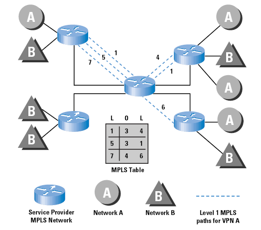
The major observation here is that this lightweight encapsulation, together with the associated notion of boundary-determined transit paths, provides many of the necessary mechanisms for the support of VPN structures [9]. MPLS VPNs have not one, but three key ingredients: (1) constrained distribution of routing information as a way to form VPNs and control inter-VPN connectivity; (2) the use of VPN-IDs, and specifically the concatenation of VPN-IDs with IP addresses to turn (potentially) nonunique addresses into unique ones; and (3) the use of label switching (MPLS) to provide forwarding along the routes constructed via (1) and (2). The generic architecture of deployment is that of a label-switched common host network and a collection of VPN environments that use label-defined virtual circuits on an edge-to-edge basis across the MPLS environment. An example is indicated in Figure 4, which shows how MPLS virtual circuits are constructed.
Numerous approaches are possible to support VPNs within an MPLS environment. In the base MPLS architecture, the label applied to a packet on ingress to the MPLS environment effectively determines the selection of the egress router, as the sequence of label switches defines an edge-to-edge virtual path. The extension to the MPLS local label hop-by-hop architecture is the notion of a per-VPN global identifier (or Closed User Group - CUG) identifier, as defined in [5]), which is used effectively within an edge-to-edge context. This global identifier could be assigned on ingress, and is then used as an index into a per-VPN routing table to determine the initial switch label. On egress from the MPLS environment, the CUG identifier would be used again as an index into a per-VPN global identifier table to undertake next-hop selection.
Routing protocols in such an environment need to carry the CUG identifier to trigger per-VPN routing contexts, and a number of suggestions are noted in [5] as to how this could be achieved.
It should be stressed that MPLS itself, as well as the direction of VPN support using MPLS environments, is still within the area of active research, development, and subsequent standardization within the IETF, so this approach to VPN support is still somewhat speculative in nature.
As mentioned previously, encryption technologies are extremely effective in providing the segmentation and virtualization required for VPN connectivity, and can be deployed at almost any layer of the protocol stack. Because there are no intrinsically accepted industry standards for link-layer encryption, all link-layer encryption solutions are generally vendor specific and require special encryption hardware.
Although this scenario can avoid the complexities of having to deal with encryption schemes at higher layers of the protocol stack, it can be economically prohibitive, depending on the solution adopted. In vendor proprietary solutions, multivendor interoperability is certainly a genuine concern.
Although VPNs can certainly be implemented at the transport and application layers of the protocol stack, this setup is not very common. The most prevalent method of providing virtualization at these layers is to use encryption services at either layer; for example, encrypted e-mail transactions, or perhaps authenticated Domain Name System (DNS) zone transfers between different administrative name servers, as described in DNSSec (Domain Name System Security) [10].
Some interesting, and perhaps extremely significant, work is being done in the IETF to define a Transport Layer Security (TLS) protocol [11], which would provide privacy and data integrity between two communicating applications. The TLS protocol, when finalized and deployed, would allow applications to communicate in a fashion that is designed to prevent eavesdropping, tampering, or message forgery. It is unknown at this time, however, how long it may be before this work is finalized, or if it will be embraced by the networking community as a whole after the protocol specification is completed.
The significance of a “standard” transport-layer security protocol, however, is that when implemented, it could provide a highly granular method for virtualizing communications in TCP/IP networks, thus making VPNs a pervasive commodity, and native to all desktop computing platforms.
Although this article has focused on TCP/IP and VPNs, it is recognized that multiprotocol networks may also have requirements for VPNs. Most of the same techniques previously discussed can also be applied to multiprotocol networks, with a few obvious exceptions—many of the techniques described herein are solely and specifically tailored for TCP/IP protocols.
Controlled route leaking is not suitable for a heterogeneous VPN protocol environment, in that it is necessary to support all protocols within the common host network. GRE tunnels, on the other hand, are constructed at the network layer in the TCP/IP protocol stack, but most routable multiprotocol traffic can be transported across GRE tunnels (for example, IPX and AppleTalk). Similarly, the VPDN architectures of L2TP and PPTP both provide a PPP end-to-end transport mechanism that can allow per-VPN protocols to be supported, with the caveat that it is a PPP-supported protocol in the first place.
The reverse of heterogeneous VPN protocol support is also a VPN requirement in some cases, where a single VPN is to be layered above a heterogeneous collection of host networks. The most pervasive method of constructing VPNs in multiprotocol networks is to rely upon application-layer encryption, and the resulting VPNs are generally vendor proprietary, although some would contend that one of the most pervasive examples of this approach was the mainstay of the emergent Internet in the 1970s and 1980s—that of the UNIX-to-UNIX Copy Program (UUCP) network, which was (and remains) an open technology.
In addition to creating a segregated address environment to allow private communications, the expectation that the VPN environment will be in a position to support a set of service levels also exists. Such per-VPN service levels may be specified either in terms of a defined service level that the VPN can rely upon at all times, or in terms of a level of differentiation that the VPN can draw upon the common platform resource with some level of priority of resource allocation.
Using dedicated leased circuits, a private network can establish fixed resource levels available to it under all conditions. Using a shared switched infrastructure, such as Frame Relay virtual circuits or ATM virtual connections, a quantified service level can be provided to the VPN through the characteristics of the virtual circuits used to implement the VPN.
When the VPN is moved away from such a circuit-based switching environment to that of a general Internet platform, is it possible for the Internet Service Provider to offer the VPN a comparable service level that attempts to quantify (and possibly guarantee) the level of resources that the VPN can draw upon from the underlying host Internet?
This area is evolving rapidly, and much of it remains within the realm of speculation rather than a more concrete discussion about the relative merits of various Internet QoS mechanisms. Efforts within the Integrated Services Working Group of the IETF have resulted in a set of specifications for the support of guaranteed and controlled load end-to-end traffic profiles using a mechanism that loads per-flow state into the switching elements of the network [12, 13]. There are numerous caveats regarding the use of these mechanisms, in particular relating to the ability to support the number of flows that will be encountered on the public Internet [14]. Such caveats tend to suggest that these mechanisms will not be the ones that are ultimately adopted to support service levels for VPNs in very large networking environments.
If the scale of the public Internet environment does not readily support the imposition of per-flow state to support guarantees of service levels for VPN traffic flows, the alternative query is whether this environment could support a more relaxed specification of a differentiated service level for overlay VPN traffic. Here, the story appears to offer more potential, given that differentiated service support does not necessarily imply the requirement for per-flow state, so stateless service differentiation mechanisms can be deployed that offer greater levels of support for scaling the differentiated service [15]. However, the precise nature of these differentiated service mechanisms, and their capability to be translated to specific service levels to support overlay VPN traffic flows, still remain in the area of future activity and research.
So what is a virtual private network? As we have discussed, a VPN can take several forms. A VPN can be between two end systems, or it can be between two or more networks. A VPN can be built using tunnels or encryption (at essentially any layer of the protocol stack), or both, or alternatively constructed using MPLS or one of the “virtual router” methods. A VPN can consist of networks connected to a service provider’s network by leased lines, Frame Relay, or ATM, or a VPN can consist of dialup subscribers connecting to centralized services or other dialup subscribers.
The pertinent conclusion here is that although a VPN can take many forms, a VPN is built to solve some basic common problems, which can be listed as virtualization of services and segregation of communications to a closed community of interest, while simultaneously exploiting the financial opportunity of economies of scale of the underlying common host communications system.
To borrow a popular networking axiom, “When all you have is a hammer, everything looks like a nail.” Every organization has its own problem that it must solve, and each of the tools mentioned in this article can be used to construct a certain type of VPN to address a particular set of functional objectives. More than a single “hammer” is available to address these problems, and network engineers should be cognizant of the fact that VPNs are an area in which many people use the term generically—there is a broad problem set with equally as many possible solutions. Each solution has numerous strengths and also numerous weaknesses and vulnerabilities. No single mechanism for VPNs that will supplant all others in the months and years to come exists, but instead a diversity of technology choices in this area of VPN support will continue to emerge.
Thanks to Yakov Rekhter, Eric Rosen, and W. Mark Townsley, all of Cisco Systems, for their input and constructive criticism.
[1] Valencia, A., M. Littlewood, and T. Kolar. “Layer Two Forwarding (Protocol) ‘L2F’.” draft-valencia-l2f-00.txt, work in progress, October 1997.
[2] Droms, R. “Dynamic Host Configuration Protocol.” RFC 2131, March 1997.
[3] Kent, S., and R. Atkinson. “Security Architecture for the Internet Protocol.” draft-ietf-ipsec-arch-sec-04.txt, work in progress, March 1998.
[4] Additional information on IPSec can be found on the IETF IPSec home page, located at http://www.ietf.org/html.charters/ipseccharter.html
[5] Heinanen, J. “Multiprotocol Encapsulation over ATM Adaptation Layer 5.” RFC 1483, July 1993.
[6] The ATM Forum. “Multi-Protocol Over ATM Specification v1.0.” afmpoa-0087.000, July 1997.
[7] Callon, R., P. Doolan, N. Feldman, A. Fredette, G. Swallow, and A. Viswanathan. “A Framework for Multiprotocol Label Switching.” draft-ietf-mpls-framework-02.txt, work in progress, November 1997.
[8] Rosen, E., A. Viswanathan, and R. Callon. “A Proposed Architecture for MPLS.” draft-ietf-mpls-arch-01.txt, work in progress, March 1998.
[9] Heinanen, J. and E. Rosen. “VPN Support for MPLS.” draft-heinanen-mpls-vpn-01.txt, work in progress, March 1998.
[10] Eastlake, D. and C. Kaufman. “Domain Name System Security Extensions.” RFC 2065, January 1997. For further information regarding DNSSec, see: http://www.ietf.org/html.charters/dnssec-charter.html
[11] Dierks, T. and C. Allen. “The TLS Protocol—Version 1.0.” draft-ietf-tls-protocol-05.txt, work in progress, November 1997. For more information on the IETF TLS working group, see http://www.ietf.org/html.charters/tls-charter.html. See also the article on SSL in the Internet Protocol Journal, Volume 1, No. 1, June 1998.
[12] Wroclawski, J. “Specification of the Controlled-Load Network Element Service.” RFC 2211, September 1997.
[13] Shenker, S., C. Partridge, and R. Guerin. “Specification of Guaranteed Quality of Service.” RFC 2212, September 1997.
[14] Mankin, A., F. Baker, S. Bradner, M. O’Dell, A. Romanow, A. Weinrib, and L. Zhang. “Resource ReSerVation Protocol (RSVP) Version 1—Applicability Statement, Some Guidelines on Deployment.” RFC 2208, September 1997.
[15] “Differentiated Services Operational Model and Definitions.” draft-nichols-dsopdef-00.txt, work in progress, K. Nichols and S. Blake (editors), February 1998.
PAUL FERGUSON is a consulting engineer at Cisco Systems and an active participant in the Internet Engineering Task Force (IETF). His principal areas of expertise include large-scale network architecture and design, global routing, Quality of Service (QoS) issues, and Internet Service Providers. Prior to his current position at Cisco Systems, he worked in network engineering, analytical, and consulting capacities for Sprint, Computer Sciences Corporation (CSC), and NASA. He is coauthor of Quality of Service: Delivering QoS on the Internet and in Corporate Networks, published by John Wiley & Sons, ISBN 0-471-24358-2, a collaboration with Geoff Huston.
E-mail: ferguson@cisco.com
GEOFF HUSTON holds a B.Sc and a M.Sc from the Australian National University. He has been closely involved with the development of the Internet for the past decade, particularly within Australia, where he was responsible for the the initial build of the Internet within the Australian academic and research sector. Huston is currently the Chief Technologist in the Internet area for Telstra. He is also an active member of the IETF, and was an inaugural member of the Internet Society Board of Trustees. He is coauthor of Quality of Service: Delivering QoS on the Internet and in Corporate Networks, published by John Wiley & Sons, ISBN 0-471-24358-2, a collaboration with Paul Ferguson.
E-mail: gih@telstra.net