
ISP Column
Geoff Huston
March 2000
Satellite-based services pose a set of unique challenges to the network designer. Most notably, these issues include delay, noise and bandwidth. There is an inherent delay in the delivery of a packet due to signal propagation times related to the altitude of communications satellites. Geostationary spacecraft orbit 36,000 kilometers above the Earth. The propagation time for a signal to pass from an Earth station to a satellite and back is 239.6 milliseconds (ms). At the edge of a satellite's view area, this propagation delay increases to 279.0 ms. The strength of a radio signal falls in proportion to the square of the distance traveled. For a satellite link, the signal propagation distance is large and the signal becomes weak, resulting in a low signal-to-noise ratio at the receiver's end. Typical bit error rates (BER) for a satellite link today are on the order of 1 error per 10 million bits. Error control coding can be added to existing satellite services, but such coding does add further delay and does impact on useable bandwidth. The radio spectrum is a limited natural resource. There is a restricted amount of bandwidth available to satellite systems. Typical carrier frequencies for point- to-point satellite services are 6 GHz (uplink) and 4 GHz (downlink), also known as C-band; and 14/12 GHz (Ku-band). Typical C-band transponder bandwidth is 36 MHz, while Ku-band transponders are typically around 50 MHz. One satellite may carry a few dozen transponders.
When used to support IP traffic, satellite services have a number of distinctive characteristics that require special consideration.
Satellite systems are not the only environment where such characteristics are present. However, satellite systems are prone to exhibiting all three characteristics simultaneously.
There is one property of satellite systems that is also not commonly found on terrestrial-based cable services: asymmetry. Cable-based transmission systems are generally provisioned symmetrically, with identical bandwidth and delay in each direction. It is possible to provision satellite systems with asymmetric characteristics. This asymmetry may be in terms of unequal bandwidth, where there is greater capacity provided in one direction, or in the use of uni-directional (or simplex) links, where data flow is only supported in one direction. For example, a host connected to a satellite network will send all outgoing traffic over a narrow bandwidth terrestrial link (such as a dial-up modem channel) and receive incoming traffic via a high capacity shared satellite channel.
We will examine one kind of asymmetry in further detail, the use of simplex satellite links within the context of supporting backbone Internet services.
Many parts of the Internet support asymmetric traffic volumes, where more data flows in one direction than the other. This asymmetry can lead to relatively inefficient circuit utilization, when symmetric circuits are being used. In such cases the circuit may be fully utilized in one direction, while operating at between 20 to 40 percent capacity in the other. In such cases the Internet operator can achieve no higher than 60 to 70 percent total circuit utilization. This situation is quite common in the case of trans-oceanic Internet services, where the volume of incoming data commonly exceeds the amount of outgoing data. One way of providing additional transmission capacity into such a network is to augment the incoming capacity with a simplex satellite transmission service. This option provides additional capacity for the critical congestion point, while avoiding augmenting capacity where it is not needed. In many circumstances this is a highly cost effective solution for an Internet service provider (ISP).
The more general deployment of simplex link is indicated in Figure 1, where the unidirectional link is part of a connectivity fabric where traffic flowing in the reverse direction is supported along a multi-hop path. In this case router A reaches router B via a unidirectional link, while B can reach A via a path through routers E, D and C.
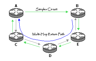
Figure 1
Simplex circuits are not readily supported in Internet environments for two major reasons. Simplex circuits raise problems in supporting link-level keep alive functions and support of routing protocols. Both these functions normally assume some level of circuit bi-directionality to function correctly.
Routers normally use a lightweight link monitoring protocol to ensure that the circuit remains up in both directions, that the circuit has not shifted into a loop back condition, and that the remote router is operational. This is undertaken by a simple counter reflection protocol undertaken at the link layer. Each router maintains a per-link counter variable and a timer. At regular intervals the counter is passed to the remote router, which responds with a reflection of this counter as well as sending its counter value. The local router increments its counter and sends this new value to the remote end, together with a reflection of the remote counter. If the router does not see a reflection of its counter value within a set interval the link is reset, and marked as unavailable. As can be seen, this basic protocol assumes link level bi-directionality. The problem with a simplex link is that this bi-directional information exchange of information is not possible, and the sender cannot tell if the link is functioning, nor if the receiver is still active.
The second problem occurs in supporting routing protocols. For one router to send traffic to an adjacent router, the router must be aware of which address prefixes are reachable via the remote router. This flow of address prefix reachability flows in the opposite direction to the normal flow of data. In simplex systems, the problem lies in determining how to support the flow of routing information when there is no reverse path for the flow of routing information.
If these two problems can be solved, the remainder of the IP configuration tasks to support a unidirectional link presents few problems. IP routing is not inherently symmetric in the first place, so that each router makes an independent choice as to the best path to the other router (an IP routing state can be considered as a directed graph, where the underlying connectivity is assumed to be a set of paired unidirectional links). Where a link presents a uniform cost metric to traffic in each direction the routing protocols will normally converge on a symmetric solution for traffic, but where the link metrics are different for traffic in either direction, the IP protocol will make an asymmetric routing choice, and traffic will use diverse paths for each direction. The unidirectional circuit case is consistent with this behaviour, and is identical, from a routing perspective to marking the cost of a link as infinite (unreachable) in one direction, while maintaining a normal link metric to the opposite direction. Therefore the deliberate construction of an asymmetric path where traffic on one direction uses a single hop link, while traffic in the other direction uses a multi-hop transit path presents no particular issues to the normal operation of IP protocols.
A number of solutions have been proposed to address the problems of link integrity monitoring and the support for routing protocols. Typically, such approaches use some form of tunnel (header encapsulation) to emulate a link-level path in the reverse direction. However this approach of a reverse path tunnel requires explicit support on the part of the equipment vendor, and the use of tunnels within a production network can impact other network design objectives.
An alternative approach is based on the observation that can be made from Figure 1 that it is possible to support a bi-directional TCP session between A and B using normal IP routing functions and the inclusion of one static route. If a static route is added to A indicating that B is reachable via the unidirectional link, then packets from A to B will flow across the unidirectional link, and packets from B to A will traverse the multi-hop reverse path. The intended functionality of this approach is that the router at the ingress of the unidirectional circuit has to stop forwarding traffic down the simplex link if the link fails or the receiver fails. The link monitoring protocol used within this approach is a component of the BGP4 routing protocol, as the BGP keepalive messages are sent at regular intervals between the two BGP peering routers.
The BGP4 routing protocol is an ideal candidate for this role:
The way in which BGP keepalive messages and routing information is used in this approach is visible through observing the intended outcome of link failure. Using a BGP4 keepalive loop which explicitly passes across the simplex circuit will ensure that the ingress router's routing advertisements are withdrawn on the event of failure of the simplex circuit or the receiver. This approach is indicated in Figure 2.
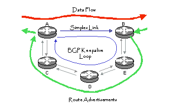
Figure 2
This approach to supporting simplex IP services was first combined with satellite services in a joint effort undertaken by Telstra and Teleglobe in early 1998. In this configuration Teleglobe was configured as the Simplex sender and Telstra as the receiver. This simplex configuration has been subsequently used in many other Internet infrastructure configurations.
The Telstra (receiver) configuration uses a Cisco router connected as the receiver of a 45 Mbps unidirectional satellite circuit. This router is located within Telstra's Internet services equipment racks in Australia, and a local circuit extension was provided from the equipment rack to the earth station. The router was also connected to Telstra's Internet backbone via a local LAN connection. The Teleglobe (sender) configuration for the unidirectional transmitter is very similar, again using Cisco equipment as the router, with a connection into Teleglobe's backbone network. The sender islocated in North America and the receiver in Australia.
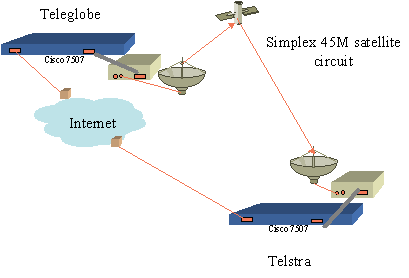
Figure 3
The reverse Internet path (Australia to North America) is a multi-hop multi-provider transit path.
Telstra has a number of full duplex high capacity undersea cable circuits which are terminated with connections to various North American Internet providers. This type of configuration, where the reverse cable path terminates with a different Internet service provider, and the entire loop path is a multi-provider multi-hop path, is the most challenging to design, and the most challenging to achieve good performance. When possible, a configuration that has the cable and satellite paths terminating at the same location, with the same provider, is an easier configuration to manage.
Both Telstra and Teleglobe use Cisco routers to manage the simplex link, using standard versions of Cisco's IOS software. The two routers are configured to use multihop BGP-4 peering using the loopback addresses as the peer addresses for the BGP-4 session. Telstra passes to Teleglobe the routes to announce to the Internet from the Teleglobe router via the BGP session. While the BGP session remains active the Teleglobe router receives the Telstra routers via the BGP4 exterior route peering session, and then advertises them into the Internet. The Teleglobe router uses a static route entry for the Telstra router loopback address, and the BGP routes all use the Telstra loopback address as the next hop address. In this way, once the Teleglobe router receives a packet that is directed to one of the advertised addresses, the Teleglobe router will forward it along the simplex link to reach the next hop address. On-circuit failure the BGP session is brought down, and the Teleglobe route advertisements are then withdrawn via normal BGP4 operation.
The generic sender configuration for the circuit is shown in Figure 4.
!

!Set up a loopback address as a BGP peering address

!

interface Loopback3

ip address 3.3.3.2 255.255.255.255

!

!

! This is the interface to the Internet

!

interface Ethernet0

ip address 2.2.2.2 255.255.255.224

!

!

! This is the satellite simplex sender. HDLC is used as the link

! encapsulation protocol, with keepalive functions suppressed

! full duplex modem control signals which may prevent the line

! from coming up are suppressed

!

interface Serial0

ip address 1.1.1.2 255.255.255.252

no keepalive

ignore-dcd

!

!

! The bgp session is set to use 15 second keepalives and a 30 second holddown

! the remote BGP peer is the loopback address of the remote end

! the local BGP peer is set to the local loopback address, and the number of

! hops on the Internet transit is allowed to reach 255 in this case

!

router bgp 50

timers bgp 5 30

neighbor 3.3.3.1 remote-as 25

neighbor 3.3.3.1 ebgp-multihop 255

neighbor 3.3.3.1 update-source Loopback3

!

!

! the route to the remote peer loopback address is forced through the satellite

! circuit via this static route

!

ip route 3.3.3.1 255.255.255.255 Serial0
Figure 4
The matching receiver configuration is shown in Figure 5.
!

! Set up a loopback address as a BGP peering address

!

interface Loopback3

ip address 3.3.3.1 255.255.255.255

!

!

! this is the interface to the Internet

!

interface Ethernet0

ip address 2.2.2.1 255.255.255.224

!

!

! this is the satellite simplex receiver. HDLC is used as the link

! encapsulation protocol, with keepalive functions suppressed

! full duplex modem control signals which may prevent the line

! from coming up are suppressed

!

interface Serial0

transmit-interface Ethernet0

ip address 1.1.1.1 255.255.255.252

no keepalive

ignore-dcd

!

!

! the bgp session is set to use 15 second keepalives and a 30 second holddown

! the remote BGP peer is the loopback address of the remote end

! the local BGP peer is set to the local loopback address, and the number of

! hops on the Internet transit is allowed to reach 255 inthis case

!

router bgp 25

timers bgp 5 30

redistribute static

neighbor 3.3.3.2 remote-as 50

neighbor 3.3.3.2 ebgp-multihop 255

neighbor 3.3.3.2 update-source Loopback3

!

!

! the route to the remote peer lookback address is forced through the ethernet

! circuit via this static route

!

ip route 3.3.3.2 255.255.255.255 Ethernet0
Figure 5
The feature to note here is that a reverse path tunnel is not configured here. This omission of an explicit reverse path tunnel is regarded as a more robust solution, although care must be taken with the routing configuration at both ends to ensure that the receiver does not attempt to transmit through the serial interface. In the generic router configuration indicated above the Cisco 'transmit-interface' command is used, although with correct routing control at both ends this interface directive is unnecessary.
The time taken to detect a circuit break, and the time taken to restore a circuit will be dependant on the values used for the BGP timers for keep alive interval and hold down. With the values of 5 and 30 seconds for these two timers the test results indicated that it took 35 seconds for a break in the circuit to cause the BGP session to withdraw the route advertisements. Once the physical circuit was restored it took a further 10 seconds for the BGP session to enter an active state and commence loading routes into the remote table.
Over a 9-week measurement period the input error rate of 0.02 percent packets received with errors has been observed. The errors break down to 11 percent CRC errors, 47 percent frame errors and 42 percent overrun errors. It is noted that these errors occur in discrete bursts.
The router input queue has also dropped some packets, due to the receiver overrunning the available buffer. This drop rate is 0.0008 percent of packets over the measurement period.
Tests of an asymmetric circuit are slightly more challenging than a symmetric circuit. One approach is to measure one-way delay and loss across the simplex link. Such a measurement regime requires that the sender records both a sequence number and a clock value in the probe packet, and that the receiver uses a clock that is synchronized to the sender. In this way the receiver can note the probe packet's propagation delay and also the packet loss rate.
The environment constructed here is perhaps one of the more challenging environments where a simplex satellite circuit can be deployed. The two operators, Telstra and Teleglobe have no other direct Internet connection other than this simplex circuit. This implies that to ping across the simplex circuit, the ping packet must transit a third party network to complete the loop, so that ping-based measurements of the overall performance of the simplex circuit are actually measuring the performance of a larger traffic loop. This is indicated in Figure 6.
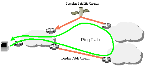
Figure 6
Overall the trials indicate that performance of this configuration is acceptable within the context of the Internet, providing an acceptable circuit platform for Internet use.
